
Magnetic Field Along The Axis of A Circular Coil Carrying Current
Procedure
Apparatus
Circular coil, compass box, ammeter, rheostat, commutator, cell, key, connection wires, etc. The purpose of the commutator is to allow the current to be reversed only in the coil, while flowing in the same direction in the rest of the circuit.
Circular coil apparatus:
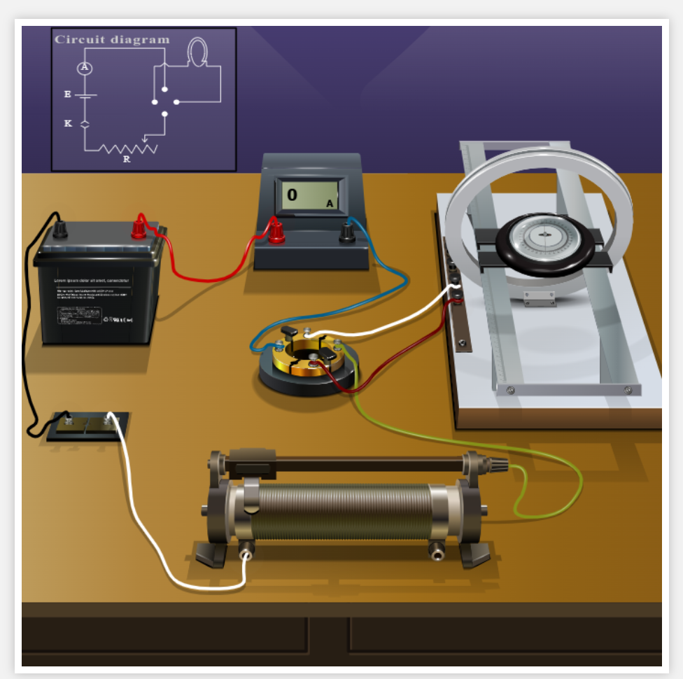
The apparatus consists of a circular coil C of 5 to 50 turns, having diameter about 10 centimeters. There is a brass frame in which the coil is wound. The frame is fitted to a stand, with its plane vertical. It can be moved along a rectangular wooden board. B is the deflection magnetometer. There is a scale fitted to the wooden board, from which the distance of the centre of the magnetic needle from the centre of the coil can be measured.
Procedure for doing the simulator
Perform the initial alignment of the apparatus.
- Click INITIAL ADJUSTMENT to open the enlarged view of the compass box.
- Using the Rotate Compass slider, rotate the compass box until its 90–90 line is exactly parallel to the plane of the circular coil.
- Once the compass box is correctly aligned, use the Rotate Apparatus slider to rotate the entire setup until the aluminium pointer (compass needle) coincides with the 0–0 line.
- Click Show Normal to return to the main experimental setup.
Make the circuit connections according to the circuit diagram displayed below.
- Click and drag each connection wire from one terminal to its corresponding terminal until all components are connected correctly.
- The INSERT KEY button will be activated when all the wires are connected properly. Click INSERT KEY to begin with the experiment.
Set the number of turns of the circular coil using the Number of Turns of the Coil slider.
Adjust the radius of the circular coil using the Radius of the Coil slider.
Set the compass position by moving the Compass Position slider to place the compass box at the desired distance from the centre of the circular coil.
Insert the key by clicking the Insert Key button to complete the circuit.
Adjust the current through the circular coil using the Adjust Rheostat slider until a suitable deflection of the compass needle is obtained.
Observe the compass deflection by clicking Zoom Compass. Read the deflection of the aluminium pointer and return to the normal view using Show Normal.
Reverse the current by clicking the Reverse Current button and again observe the compass deflection using the zoomed compass view.
Calculate the average deflection from the observations corresponding to the forward and reverse current directions.
Repeat the experiment for different compass positions while keeping the number of turns, coil radius, and current constant. Record the average deflection for each position.
| Distance from the centre, x (cm) | Left Side (Direct) θ₁ | Left Side (Direct) θ₂ | Left Side (Reversed) θ₃ | Left Side (Reversed) θ₄ | Right Side (Direct) θ₁ | Right Side (Direct) θ₂ | Right Side (Reversed) θ₃ | Right Side (Reversed) θ₄ | Mean θ (degrees) | Bₓ (T) | B₀ = Bₓ / tan θ (T) |
|---|---|---|---|---|---|---|---|---|---|---|---|
Repeat the experiment for different values of:
- Number of turns of the coil,
- Radius of the coil, and
- Current through the coil,
to study their effect on the magnetic field along the axis of the circular coil.
Select the Show Result checkbox to display the calculated magnetic field corresponding to the selected experimental conditions.
Click Reset to restore the simulator to its initial state and perform a new experiment.
Procedure for doing the real lab:
To find the magnetic field:
The connections are made as shown in the diagram and the initial adjustments of the apparatus are made as follows:
- First, the coil is fixed at the middle of the platform and the compass box is placed at the centre of the coil.
- The compass box is rotated till the 90-90 line becomes parallel to the plane of the coil.
- Then the apparatus as a whole is rotated till the aluminium pointer reads 0-0.
- Close the circuit.
- Adjust the rheostat until the deflection lies between 30 and 60 degrees. Note down the deflection of the compass needle and the current.
- Then current through the coil is reversed using the commutator and again the deflection and current are noted.
- Average the magnitude of the two deflections and calculate the magnetic field at the centre of the coil from the equation.
- Without changing the current or the number of turns, place the compass box at a particular distance from the centre of the coil. Note the deflection. Again reverse the current and average the magnitudes of the two deflections. Note the average, and the distance.
- The same procedure is repeated with the compass box at the same distance on the other side of the arm, keeping number of turns and current constant.
- Take the average of the two values of , measured on opposite sides of the coil.
- Then calculate the magnetic field from the coil using equation (3).
- Repeat for various distances.
- Draw graph of on the vertical axis vs. distance x on the horizontal axis.
To plot the graph between distance and magnetic field intensity:
T
Current, I =............ A
No: of turns of the coil, n=..............
Radius of the circular coil, r =.............. cm
Then plot the graph between distance and magnetic field intensity.
Result
Flux density due to Earth's horizontal field at the place=..........T